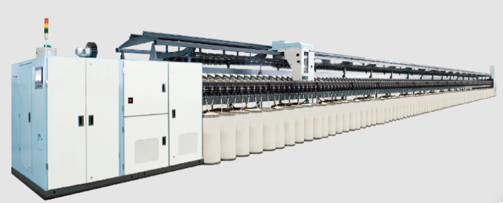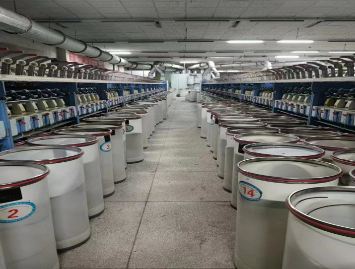
1、Whole machine structure
The rotor spinning machine is divided into three major components according to its functional components: the front, middle, and rear. The following diagram is a schematic diagram of the entire machine:
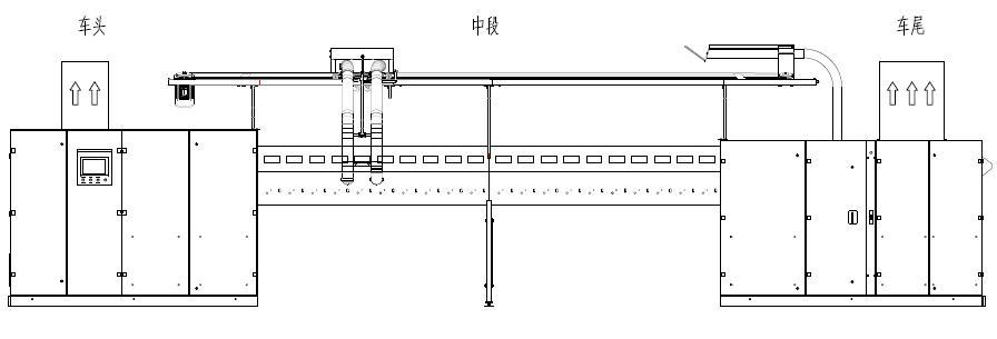 The front of the car mainly provides the transmission and electrical control of the entire machine;
The middle section is composed of spinning-related units, with a number of segments ranging from 1 to 30;
The rear of the car is mainly equipped with a negative pressure system, which collects impurities, flowers, etc, during the spinning process. Generally, customers will install blowing and suction carts according to dust removal requirements.
2、 Front-end components
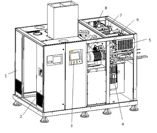
The main functional components of the front of the car are:
2.1 Electrical box: The electrical box is distributed on both sides of the front of the car. The left side is the frequency converter cabinet.
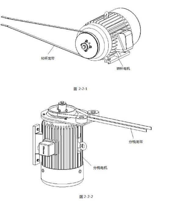
2.2 Rotary Cup and Sorting Dragon Belt Transmission: The rotating cup conveyor belt and the combing conveyor belt are directly driven by the belt pulley on the motor, and the speed is continuously adjusted by the frequency converter, bidding farewell to the trouble of replacing the belt pulley in the past. ( Figure 2-2-1 Figure 2-2-2)
2.3 Electronic servo lateral movement
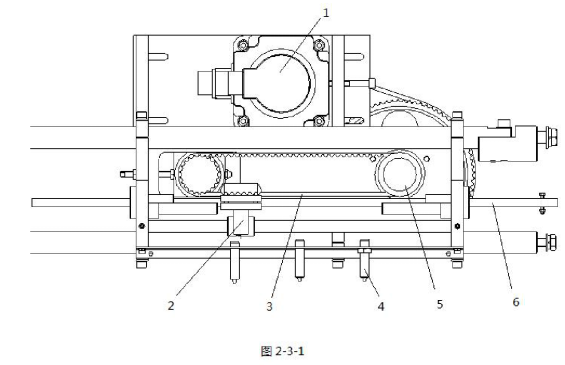
Electronic servo lateral movement replaces traditional mechanical cam boxes, with the advantages of small space occupation, convenient maintenance, and high cost
Low and precise control, with good yarn roll forming. The entire mechanism has a simple structure and is driven by a servo motor (1). The stepper wheel (5) and synchronous belt (3) drive the slider (2) to move back and forth, and the yarn guide rod (6) is connected to the guide in the middle section. The yarn rod realizes the guiding motion of the yarn.
2.4 Transmission of yarn guide shaft and winding shaft
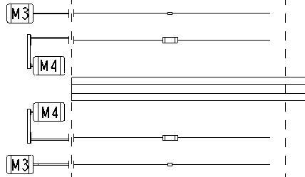
The yarn guide motor M3 directly drives the yarn guide shaft, and the winding motor M4 is slowed down by the first stage synchronous pulley group. Drive the winding shaft.
3. Middle section components
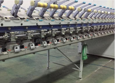
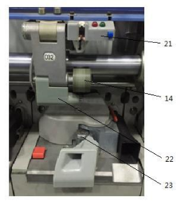
3.1 Air duct: Composed of process air duct and exhaust air duct
3.2 Tube rack and semi-automatic joint
3.3 Winding shaft, yarn guide shaft, yarn guide rod, and micro moving rod
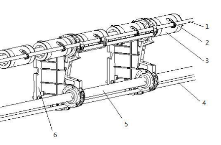
1. Guide rod 2. Guide nozzle 3. Winding roller 4. Micro rod 5. Guide shaft 6. Bearing support frame
4. Rear components
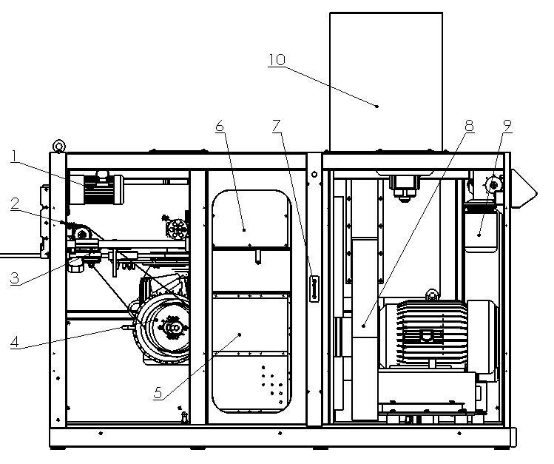
The left-side structure of the rear of the car is as follows:
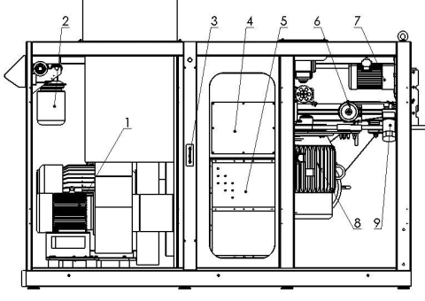
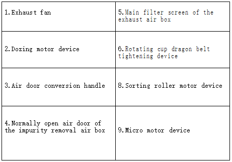
The structure on the right side of the rear of the car is as follows:
5. Spinners
The spinner is the core of the rotor spinning
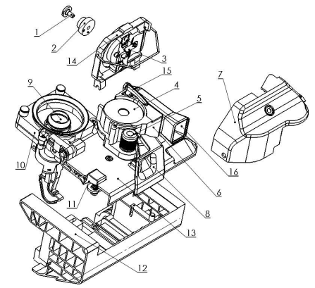
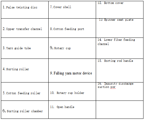
- False twisting disc Upper transfer channel 3. Yarn guide tube
- Sorting roller 5. Cotton feeding roller 6. Sorting roller chamber 7. Cover shell
- Cotton feeding port 9. Rotary cup 10. Rotary cup holder 11. Open handle 12. Bottom cover 13 Spinner seat plate
- Lower fiber feeding channel 15. Sorting rod handle 16. Impurity discharge suction por
Equipment parameters:
1. Number of ingots: 120/168/192
2. Exhaust spinning box, spindle pitch: 230MM.
3. Suitable yarn density: 100-14.7
4. Suitable fiber length: 20-40MM, not less than 20MM.
5. Feed line density: 5000-2200
6. Rotor diameter: Φ 36 mm. Speed 30000-70000. r/min
7. Twist: 258-3060T/M
8. Winding speed: 20-116R/min
9. Tube size: 300 * 150MM
10. Suitable spinning count: 32-19s
11. Total power: 139kW
12. Equipped with an intelligent digital convenient connector system
13. The process fan is driven by variable frequency control
14. The exhaust fan is driven by variable frequency control
15. The design adopts a dual exhaust fan at the front and rear of the vehicle, making the negative pressure more stable and suitable for 100% waste cotton.
16. The independent yarn guiding and winding roller motors on both sides of the machine are driven by frequency conversion control
17. The independent spinning cup motors on both sides of the machine are driven by variable frequency control
18. The left and right independent carding roller motors on both sides of the machine are driven by variable frequency control
19. Equipped with a single spindle stepper motor to independently drive cotton feeding
20. Convenient connector system
21. When the yarn breaks, the creel automatically lifts, and the bobbin leaves the winding roller